LCI Furnaces
LCI Furnaces
LCI Furnaces
INDUSTRIAL FURNACE DIVISION
INDUSTRIAL FURNACE DIVISION
INDUSTRIAL FURNACE DIVISION
TEC-504
Furnace RS-485 COM Connections
![]()
1.0 Scope
1.1 Instructions for RS-485 2-Wire communication between furnace controllers and I/O rack brains. Applies to all FurnacePros, RTC Radiant Technology, and GreenBridge Technology furnaces with Opto22 control systems.
2.0 Equipment Affected
2.1 Furnace controllers (PAC-S and LCM4 Controllers)
2.2 PAC-SB1, B3000-B and B3000 brains
3.0 General
3.1 RS-485 also known as EIA-485 is a common serial communication method for connecting furnace controllers with the input/output rack brains. When implemented correctly, RS-485 is a robust protocol that will support large networks over long distances. Since it is differential, it resists electromagnetic interference from motors and other electrical equipment.
3.2 Unlike RS232, with RS485 the common zero is NOT used as a signal reference. Differences in ground level of the RS485 transmitter and receiver do not cause any problems because RS485 signals are floating. Each signal is transmitted over a Transmit Tx+ line and a Receive Rx+ line. The RS485 receiver compares the voltage difference between both lines, instead of the absolute voltage level on a single line. This method prevents the existence of ground loops, a common source of communication problems. The best results are achieved if the Tx and Rx lines are twisted.
3.3 In furnace applications, the furnace controller (Classic Controller, LCM4, PAC-S) acts as a master node which sends queries or commands over the RS485 bus. All other nodes (B3000, B3000-B or G4 bricks or EM system boards) receive these data. Depending on the information in the sent data, zero or more nodes on the line respond to the master controller.
4.0 Guidelines
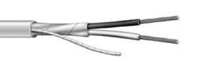 |
| Figure 3.3.1 Recommended COM Cable |
4.1 Cable. The communication cable must consist of a twisted pair of wires. Twisted cable provides a high degree of noise immunity. A third wire (untwisted) can serve to connect device commons. Factory standard cable consists of a black and white shielded twisted pair with an untwisted drain wire.
4.2 Daisy Chain Only. The devices must be wired as a daisy chain. Daisy chain is a wiring scheme in which multiple devices are wired together in a chain sequence starting from the master controller (Classic Controller, LCM4, PAC-S) to the second device (1st Brain or EM board) to the third device (2nd Brain or EM board) and so on to the last device. No tees, branches, ring or star configuration is allowed. No excess cable can extend beyond the last device. Although not mandatory, it is good practice to always wire the master device to the node with the lowest address first. Then wire from that device to the device with the next higher address and so on, terminating at the device with the highest address.
4.3 Common and Ground. Do NOT ground either conductor of the twisted pair. Commons can be connected together, but not to earth ground (see shields).
4.4 Shields. Connect all shields (if any) to the COM terminals. Make sure the shields are NOT grounded. The voltage between the COM terminals on the I/O devices cannot exceed +12 Vdc or -7 Vdc, so if shielded cable in not used, connect all COM terminals together with an untwisted third wire (drain wire if available) if there is excess voltage between the COM terminals of various I/O brains or G4 rack. In the factory, wire all RS485 commons together using the untwisted bare drain wire in the bundle.
4.5 Wire colors. The following wire colors are preferred.
| Table 4.5.1 Device COM Connection Wire Colors | ||||
| Device | Port | White | Black | Drain/shield |
|---|---|---|---|---|
| PAC-S1 | Port 2 10-pin connector | pin 1 | pin 2 | pin 3 |
| PAC-S2 | COM2 | pin 1 | pin 2 | pin 3 |
| PAC-SB1 | Com port | TX/RX+ | TX/RX- | COM |
| LCM4 | COM2 | TX2 | RX2 | <middle> |
| B3000/B3000-B | Com port | TX/RX+ | TX/RX- | COM |
4.6 Power Supplies. For trouble free RS485 communication, use isolated power supplies to run the RS485 transceiver. Make sure the power supply has no ripple and conforms to the following specifications in TEC-550 Power Supply Voltage Settings. All 5 Vdc power supply grounds shall be connected together. All 24 Vdc power supply grounds shall be connected together. Do not connect the 5 Vdc or 24 Vdc power supply common to earth ground.
4.7 Baud. Set to 115,200 baud for most furnace applications.
| Table 4.7.1 Baud Settings | ||
| Device | Location | Setting |
|---|---|---|
| PAC-S1 | - - | pin 1 |
| LCM4 Controller | Faceplate jumpers | H0, H1, B0=OFF, B1-3=ON |
| PAC-SB1 | Baud Rate Switch | Switch to D |
| B3000-B Brain | Baud Rate Switch | Switch to D |
| B3000 Brain | Baud Jumpers | Jumpers on 1,2,3 |
4.8 Termination. Only the first device (the master controller) and last device are terminated.
| Table 4.8.1 Termination Settings | |||
| Device | Location | MIddle | End |
|---|---|---|---|
| PAC-S1 | Dip switches | n/a | All ON |
| LCM4 Controller | Internal jumpers | n/a | CFG2/JP1 & CFG3/JP2 Jumpers on 2,4,5 |
| PAC-S1 | Dip switches | All OFF | ON, OFF, ON |
| B3000-B Brain | Dip switches | All OFF | ON, OFF, ON (All ON w/PAC) |
| B3000 Brain | Term jumper | none | Jumper n 1 |
5.0 General
Common configurations and preferred wiring schemes.
5.1 LCM4 - 1 SNAP RACK.
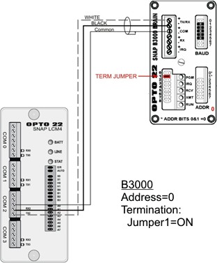 | 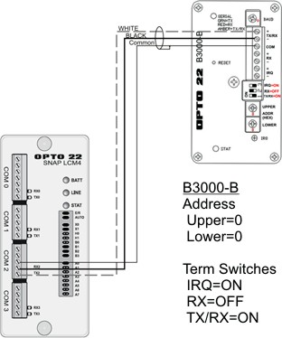 |
| Figure 5.1.1 LCM4 with one B3000 Brain | Figure 5.1.2 LCM4 with one B3000-B Brain |
5.2 LCM4 - 2+ SNAP RACKs
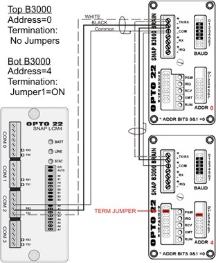 | 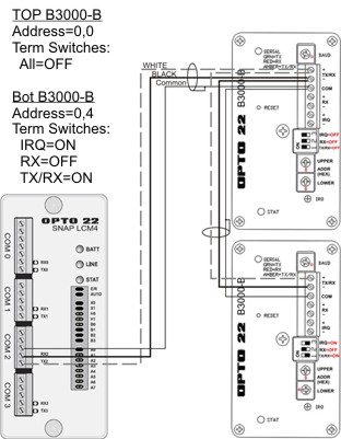 |
| Figure 5.2.1 LCM4 with two B3000 Brains | Figure 5.2.2 LCM4 with two B3000-B Brains |
5.3 LCM4 - 2+ SNAP RACKs Mixed Brains.
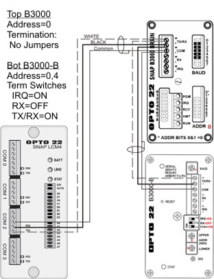 | 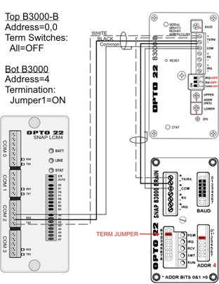 |
| Figure 5.3.1 LCM4 with one B3000 and one B3000-B Brain | Figure 5.3.2 LCM4 with one B3000-B and one B3000 Brain |
5.4 PAC-S to B3000-B Brains
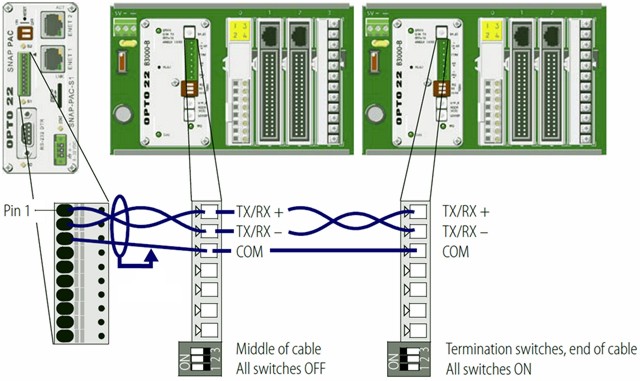 |
| Figure 5.4.1 PAC-S1 with Multiple B3000-b Brains |
5.5 PAC-S to SB-Series Brains.
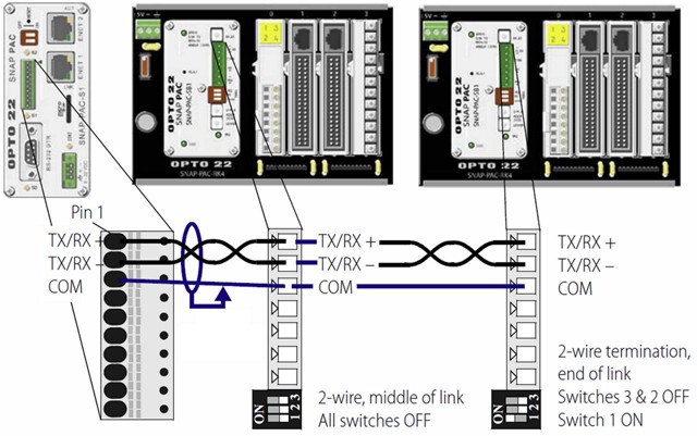 |
| Figure 5.5.1 PAC-S1 with multiple SB-1 Brains |
